Control any GPIB Interfaced Device via USB with Linux

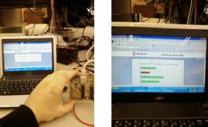
As part of an ongoing project to allow an Agilent/HP 4192A low frequency impedance analyzer to communicate with a modern netbook or PC via USB, I designed a generic interface class that allows any application designer to control his or her old instruments, such as DMMs, SPAs, and so on, using a ProLogix GPIB controller and some simple Linux software I wrote.

I’m designing the GUI with QT, and am working on creating a generic application that can interface with several different HP/Agilent instruments. I may consider re-writing it and releasing it as open source software, dependning on interest in the project. So far it has a customized GUI for each instrument that it supports. At this point, it supports automatic data acquisition from an HP 4155C semiconductor parameter analyzer (SPA) and the 4192A impedance analyzer I’ve been working with.

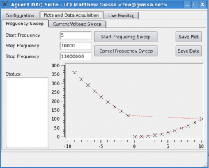
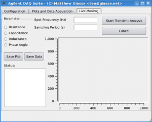
In the case of the impedance analyzer, not only is data acquisiton supported, but so are automated frequency sweeps on [5Hz, 13MHz] and current-voltage sweeps. Thanks to the features of Qwt, it rapidly generates plots, and even has a “live monitor” feature, which shows the transient response of a dielectric under study using an ECG-style plotting feature. If I get a chance to work with more instruments of these sorts, I will definitely consider designing a toolkit or application suite for these devices.

Frequency sweep example

Frequency sweep example

"Live monitor" plotting

"Live monitor" plotting

Slackware 12.2 Linux on an SDHC Card on a Dell Mini 9 Netbook (w/ Windows XP already installed)

Some time back I managed to get a hold of a shiny new Dell Inspiron Mini 9 Netbook. It’s been a great tool, helping me with my day-to-day work considerably. The only downsides to this device are that it comes with a maximum of 1GB RAM installed, and the largest available solid state drive I could get for it was 16GB. A larger solid state drive is at least a few hundred dollars, while an SDHC card can be purchased for a fraction of the cost. There are already several otherarticles available on Google showing one how to increase the amount of RAM, so I won’t cover that here.

LILO on my Mini 9

LILO on my Mini 9

What I found was that 8GB per OS was not enough for me to have both Windows XP and Slackware Linux installed onthis one machine and still have enough room to use the machine as I wanted. Windows, Microsoft Office, the .NET Framework 3.5, plus updates for all of these products quickly reduced the free space on my 8GB Windows partition to nothing. So, I set out to setup my machine so that I could have Windows running off of my 16GB solid state drive, and run Slackware 12.2 off of an SDHC card.

Before proceeding, please note that this is intended to be an overview of what I did to make this setup work on my netbook. It is not intended to serve as a tutorial to inexperienced users. This document is provided “as-is”, with no warranty, implied or otherwise. If following this document causes data loss, or your machine to crash, it’s your problem, not mine. Finally, if you found this useful, please link to it, rather than simply dump a copy of it on a forum. Thanks!

Now that that’s out of the way: the whole procedure is reasonably straightforward. All you’ll need to do this is as follows:

  • A means to boot your netbook from an optical drive. There are portable USB optical drives for netbooks which you can pick up for about $90-$110 (CAD) from most computer dealers or online. I just bought a Vantech ATA/USB adapter for $15, and a cheap DVD-Combo unit for $20 as well. Both work fine. You can also try to boot from a USB installer. Guides on how to build a bootable USB thumbdrive to install Slackware are available at http://connie.slackware.com/~alien/
  • An initrd.gz (Initial Ram Disk; More info here: http://slackware.osuosl.org/slackware/README.initrd)
  • The initrd.gz file MUST have the following modules at a minimum: ext3, mmc_core, sdhci, sdhci-pci, mmc_block
  • There are two ways you can go about doing this: a) download the pre-made initrd.gz file from here (right-click->”Save As”):initrd.gz
  • Or b) just create it on a machine already running Slackware 12.2; Just cd to the /boot directory, backup the existing initrd.gz file (if it exists), and simply execute: mkinitrd -c -k 2.6.27.7-smp -m ext3:mmc_core:sdhci:sdhci-pci:mmc_block
  • Now just copy this new initrd.gz file to something like a USB thumbdrive, and you’re ready.
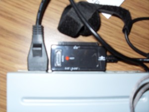
Vantech ATA/USB Adapter

Vantech ATA/USB Adapter

Now, what I did first was to format the solid state drive, and install Windows XP on it (optional),being sure to leave at least 200MB of unpartitioned space available. I then inserted the SDHC card into the slot in the side of the Mini 9 netbook. From here, I boot the Slackware 12.2 installation DVD, let it boot and login as root.

The solid state drive is picked up as /DEV/HDA immediately. So, now we can just create a Linux partiion on it by doing:

cfdisk /dev/hda

Create a new partition in the 200MB free space we left using the cfdisk utility. Make sure that it’s of type 82 (Linux), and be sure to “write” before quitting. Now, you should see /dev/hda1 and /dev/hda2 after running:

fdisk -l

Now we format this partition as ext by running:

mke2fs -j /dev/hda2

This will be our boot partition. Now, we need to access the SDHC card so that we can install Linux on it. cd to the /mnt directory, and do the following:

cd /mnt

mkdir  mmc  dvd  boot  usbdrive

mount /dev/hda2 /mnt/boot

mount /dev/sr0 /mnt/dvd

This will create mount folders for the optical drive (note that on your machine, you may have something other than /dev/sr0, such as /dev/scd0, etc). It will also mount our boot partition as well. Now, we need to get the modules for SDHC connectivity up and running. We’ll copy the kernel modules from the installation DVD, and dump it in the root folder (which is really just a ram disk at this point, since we’re still in the installer)

cp /mnt/dvd/slackware/a/kernel-modules-smp-2.6.27.7_smp-i686-1.tgz /

tar zxvvf kernel-modules-smp-2.6.27.7_smp-i686-1.tgz

cd /lib/modules/2.6.27.7-smp/kernel/drivers/mmc

insmod core/mmc_core.ko

insmod host/sdhci.ko

insmod host/sdhci-pci.ko

insmod card/mmc_block.ko

This will install all the modules we need to access the SDHC card. Now, we need to make a device node for the SDHC card and any partitions we want on it (I actually used only 6GB of my 8GB card, and the rest I set aside for a FAT32 partition so that I could access data stored there by both Linux and Windows XP). So, to create the device nodes:

mknod /dev/mmcblk0 b 179 0

mknod /dev/mmcblk0p1 179 1

mknod /dev/mmcblk0p2 179 2 ***OPTIONAL

cfdisk /dev/mmcblk0

In cfdisk, first setup a Linux partition like before. If you want to setup a FAT32 partition, you can do that now as well. Now, you’re all set. I wouldn’t bother setting up a swap partition on the SDHC card. You’re likely to burn it out, and SD cards are terribly slow to be using for paging. So, just run:

setup

And install Slackware as you normally would (to the mmcblk0p1 partition). Don’t bother with lilo right now, it won’t work. Once Slackware setup is finished, exit the installer, but do NOT reboot yet. We need to setup LILO so that we can boot this installation of Linux we just finished installing. So, first let’s mount our SDHC card containing the new Linux installation:

mount /dev/mmcblk0p1 /mnt/mmc

mknod /mnt/mmc/dev/mmcblk0 b 179 0

mknod /mnt/mmc/dev/mmcblk0p1 b 179 1      ***We shouldn’t have to do these steps, but for some reason it just works

Now, insert the USB thumb drive contraining the  initrd.gz file into a USB port on your machine. Unless you have additional SATA devices already connected (now why would you do that?) you should be able to mount the USB thumbdrive with:

mount /dev/sda1 /mnt/usbdrive

cp -r /mnt/mmc/boot/* /boot/

cp /mnt/usbdrive/initrd.gz /boot/

umount /mnt/usbdrive   ***you can remove/eject the USB thumbdrive at this point

Now that all the files we need are in place, we just need to edit our lilo.conf file.

vi /mnt/mmc/etc/lilo.conf

Mine looks like the listing below, I’d recommended the same for you. You can just copy and paste this in, or re-type it, whatever works for you.

lba32

boot = /dev/hda

append=” vt.default_utf8=0″

prompt

timeout = 50

#VESA framebuffer console @ 800x600x32k

vga=787

#Windows bootable partition config begins

other = /dev/hda1

label = WindowsXP

table = /dev/hda

#Windows bootable partition config end

#Linux bootable partition config begins

image = /boot/vmlinuz

initrd = /boot/initrd.gz

root = /dev/mmcblk0p1

label = Slackware12

read-only

#Linux bootable partition config ends

Now that the lilo configuration file is setup, all that’s left is to install LILO.

/mnt/mmc/sbin/lilo -C /mnt/mmc/etc/lilo.conf

You will likely get 3 warnings, no errors, and we’re all set. From here you can simply reboot the PC, and use LILO to boot either of Windows XP or Slackware 12.2

Enjoy!

Wireless Ultra-Small Solar Panel Charge Controller Interface (w/ Integrated Web Server)

Earlier in the year I had to finally take my engineering capstone course. This involves forming a team of at least 4 engineering undergraduate students, deciding on a commercially viable product that could be designed to improve on some existing method or system, and implement it, along with providing all details.

One of our team members, formerly a coop student with Analytic Systems (http://www.analyticsystems.com) noted that a possible enhancement to the SolarMax Charge Controller system designed by Analytic Systems, would be to allow for wireless control of the device.

So, what features would this system need? Well, after consultation with Analytic Systems, it was agreed that we would be able to have access to a SolarMax Charge Controller, and all the tools necessary to get the job done. The system would have to do the following:

  • Send/receive commands and data wirelessly between the SolarMax device, and a centralized hub which we would also design
  • Implement a fault-tolerant protocol, with the ability to encrypt the data
  • The remote device connected directly to the SolarMax device must be able to transmit data at a distance of at  least 100′
  • The central hub would have an LCD and pushbutton interface, along with LEDs to indicate data transfer, acknowledge user input, and so on

We were able to get a great head start in the implementation stage, as we designed our own circuit boards from scratch, and fabricated them using the toner transfer method and acid etching all the boards ourselves. Combined with weeks of organized coding and development, our final product not only met the initial requirements: we managed to design an entire embedded web server into the central hub (using the PIC24F and ENC28J60 chips, courtesy of Microchip Technologies), which featured Ajax-based dynamic web pages which provided up-to-the-second information from the remote unit. We even managed to configure a basic FTP server with authentication on the micro web server as well, allowing for us to possibly design the system for remote report generation and retrieval in the future.

In addition to this, we managed to extend the range of the device well beyond our initial expectations. Using low power wireless transceiver chips from Linx Technologies, we were able to control the remote SolarMax device with the central hub unit from over 200′ away. With the central hub connected to a wireless router, the project was even more impressive as we controlled the entire system with an iPhone.

Included below is a collection of images summarizing our project and it’s design:

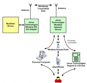
System Overview: Essentially, our product works as a wireless bridge to connect the SolarMax charge controller to a central hub which we also designed. The hub allows for multiple interfaces, including direct access via LCD and pushbutton interface, or remote connection via a networked PC or SmartPhone.

System Overview: Essentially, our product works as a wireless bridge to connect the SolarMax charge controller to a central hub which we also designed. The hub allows for multiple interfaces, including direct access via LCD and pushbutton interface, or remote connection via a networked PC or SmartPhone.

Me acid etching a PCB. Even though we used the toner transfer method, the boards came out perfectly.

Me acid etching a PCB. Even though we used the toner transfer method, the boards came out perfectly.

One of our testing boards. We built several boards so that each of us could test one in our spare time.

One of our testing boards. We built several boards so that each of us could test one in our spare time.

Testing our initial prototype. Were glued to the DMM and oscilloscope for days at some points.

Testing our initial prototype. Were glued to the DMM and oscilloscope for days at some points.

Our redesigned project using a higher quality PCB from Digikey. The design was already small, at less than 4"x3". Not bad considering it has an entire web server running on it, plus interfaces with our wireless transceiver, LCD, and push button circuits

Our redesigned project using a higher quality PCB from Digikey. The design was already small, at less than 4"x3". Not bad considering it has an entire web server running on it, plus interfaces with our wireless transceiver, LCD, and push button circuits

Our final project, connected to a wireless router and being controlled via a PC. We later connected several iPhones to it concurrently and it worked flawlessly.

Our final project, connected to a wireless router and being controlled via a PC. We later connected several iPhones to it concurrently and it worked flawlessly.

MRI Analysis Suite

After taking a course in biomedical signal and image processing, I took a strong interest in MRI and CT analysis techniques. As part of independent research, I have taken on an interesting project: designing an entire MRI analysis suite. Most of the project is done in MATLAB, but as development continues, I may consider rewriting it in another language so that I can distribute the binary for anyone to use.

So far, this program imports a MAYO 7.5 HDR file, and allows for several common image processing operations to be applied to it, including:

  • Filtering (eg: blurring, median, mode, mean, sharpening)
  • 3D edge detection via a 3D Sobel algorithm
  • 3d flood fill operations (this was an undertaking on its own; basic stack-based and recursion-based algorithms take minutes, even hours, on large MRI data sets; I successfully designed a fast, queue-based, algorithm that is essentially a 3D extension of the classic scanline flood fill algorithm)
  • Segmentation (via a Fuzzy C-means algorithm I designed)
  • Gamma correction
  • Noise removal (salt & pepper, Gaussian noise)
  • Statistical analysis (ie: calculating the volumes of cerebrospinal fluid, white matter, gray matter, and extracranial voxels in MRI data)

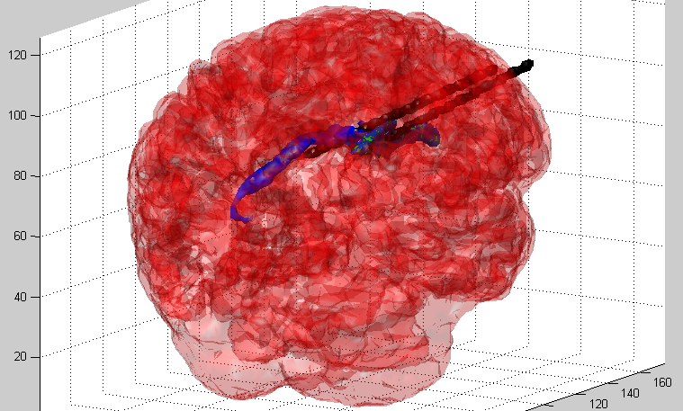
What really made this project intesting is the specialized features I’ve added. The most recent one detects the ventricles of the brain via a statistical method and an arbitrary shape detection algorithm, providing two ways to ensure accurate results. It can separate them from the rest of the brain, along with other major portions of the brain.

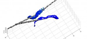
To make things even more interesting, the primary axis of any portion of the brain can be generated and displayed as a 3D vector. This is from a PCA algorithm I designed to allow for the brain to be oriented in RPI format.

I will continue developing and optimizing this collection of MRI analysis tools. I amy even release the source for them in the coming months too.

Some samples of the program in action are shown below.

Brain + Ventricles + PCA 3

Red - Brain Tissue; Blue/Green - Ventricles; Black - PCA/Primary-Axis Vectors

The brain (translucent, red) with the ventricles of the brain in blue.

The brain (translucent, red) with the ventricles of the brain in blue.

Ventricles and Primary Axis Vectors

Ventricles and Primary Axis Vectors